Introduction of the Hanifa Formation
This section describes the high frequency sequence analysis of the 500 foot thick Hanifa formation (seal, source, and reservoir). This was undertaken to provide a better understanding of the configuration of the Arabian basin, its depositional history, leading to the development of a better reservoir model from which hydrocarbon extraction might become more efficient. Production engineers should be able take advantage of the identified fluid layers when planning production strategies.
Click thumbnail images for display of large images. Right click on large images for better resolution.
The basinal lithofacies also functions as a seal for the underlying Hadriya reservoir. The shallow shelfal skeletal conglomerates of this formation constitute the bulk of the Hanifa Reservoir of the Berri giant oil field of eastern Saudi Arabia. Both reservoir and source lithofacies accumulated contemporaneously but in a different part of the basin.
The Hanifa formation derives its name from the Wadi Hanifa, 60 km SW of Riyadh where the type section was originally measured by Steineke in 1937 (Powers et al., 1966). The lithology of the Hanifa Formation has been discussed briefly in the Hanifa Tectonics section. A greater emphasis is now placed on the sequence stratigraphic framework from the perspective of sea level, paleo geography; and high frequency cycles (.01 - .1 million years).
Geological Setting
The late Oxfordian to early Kimmeridgian Hanifa source Rock was deposited in the intrashelf basin of the differentiated Arabian basin. These deposits are mostly low-energy, laminated, dark, organic-rich lime muds deposited under anoxic bottom-water conditions. To the north of this intrashelf basin, high-energy, shallow-water grainstones and evaporitic peritidal sediments accumulated across the Rimthan arch (McGuire et al., 1993). To the east, the continental margin separated the platform from the open ocean in which little or no deposition took place (Murris, 1980).
During the Hanifa Fformation deposition, the Arabian basin transition from the northern shelf-margin into the southern intrashelf sag was gradual. The northern margin of the basin by the Rimthan arch was characterized by shallow-marine oolitic and peloidal grainstones. Koepnick et al. (1994) indicated that there were indications of peritidal conditions and islands developing along the northern transition between the Rimthan arch and the Gotnia basin to the north. The basin gradually and gently dips to the southwest (slope < 0.5 degrees) forming a ramp-like depositional surface with a deeper gentle intrashelf depression to the southwest. This is indicated by a gradual southwestward thinning of the carbonate deposits and thickening of the evaporite deposits (salinas) in later regressive and restrictive stages. The Hanifa formation is overlain by the Lower Kimmeridgian shallow-water Jubaila formation.
Intrashelf Basin Characteristics and Development
The late Oxfordian-early Kimmeridgian Hanifa Formation accumulated in a relatively shallow depression that represents a classic example of an intrashelf basin which formed within the interior of an extensive broad epeiric, shallow water carbonate platform, the "Arabian Hanifa Intrashelf basin" (Aigner et al., 1989). These authors suggested the topography of this basin was responsible for the deposition of prolific source Rocks in the Upper Jurassic of Eastern Arabia. This Hanifa intrashelf basin was separated from the open ocean to the East by a high-energy platform margin. Aigner et al. (1989) related the development of this Hanifa intrashelf basin to a major rise in eustatic sea level, or transgression, which drowned the isostatically sagging platform interior. Like other similar Mesozoic basins, the Hanifa basin was short-lived and was filled during a subsequent sea-level cycle. The role of eustatic sea level was magnified by the tectonically stable character of the region of the eastern margin of the Arabian plate. Most of the infill of the intrashelf basins consists of storm-generated sediments that included shales with thin beds of quartz sand and lime silt derived from the surrounding platforms (Read, 1985, and Droste, 1990). These storm-generated fills are often upward-coarsening and upward-fining sequences (Read, 1981). Source Rocks tended to be deposited in the deepest part of the basin where organic-rich sediments accumulated under anoxic conditions that lead to the preservation of the organic matter. Beside the Hanifa intrashelf basin, other typical examples of this kind of basin fill include the Lower Cretaceous Shuaibah basin of the U.A.E. and Saudi Arabia (Alsharhan and Nairn, 1997), the Middle Cretaceous Natih formation of Oman (Van Buchem, 2002), the matching Mishrif basin of the central offshore UAE (Alsharhan and Nairn, 1997), and the Cambrian of the southern Appalachian (Markello and Read, 1982).
Climate
Throughout the Late Jurassic, the Arabian basin was characterized by a very high rate of carbonate productivity in which a high organic content was preserved in the deeper anoxic regions of the basin. This high productivity has been attributed to the arid climate and a major wind direction from the southeast, which concentrated organic material in a narrow seaway (Irvine et al., 1974).
How intrashelf basins form
There are many explanations for the formation of intrashelf basins, but most of these basins appear to form on the shallow passive stable margins of plates. Here these shallow margins are extremely susceptible to the effects of marine transgression, particularly since in such settings tectonic subsidence tends to be minimal and the resulting sedimentary fill geometries are largely the products of sea-level variations (Aigner et al., 1989). Often these intrashelf basins develop as a result of a rapid eustatic sea level rise in which carbonate margins build up around an isostatically sagged deeper basin floor while the sedimentary fill lags at a slower rate of sedimentation (Read, 1985). As indicated above most intrashelf basins are short-lived and may be filled during the succeeding transgression event.
Intrashelf basin location and extent
 The Qatar Arch separates the Arabian basin from the Rub' Al-Khali basin to the south (Southern Gulf basin of UAE and Qatar). The Rimthan Arch separates the Arabian basin from the Gotnia basin to the north (Kuwait and Iraq). During the upper Oxfordian and lower Kimmeridgian, these intrashelf basins were anoxic and the site of the accumulation of low-energy, organic rich lime mud (McGuire et al., 1993).
Previous work
There are only a few publications that deal with sequence stratigraphy of the Hanifa formation. Among these, Murris, (1980) recognized that the source Rocks for the upper Jurassic Arabian reservoirs were deposited in an intrashelf basin on the Arabian platform that was flooded by a major transgression initiated in the upper Middle Jurassic (late Oxfordian to early Kimmeridgian). These highstand carbonate deposits "kept up" with the rising sea level, finally surpassing the rate of rise and prograded seaward during the late stages of a sea level highstand. The later stages of the highstand (of the 2nd order eustatic cycle) were characterized by increasingly more regressive deposits (the Arab formation) and were finally capped by extensive evaporites (the Hith formation) that accumulated during the arid climate of the next sea level lowstand.
Ayres et al. (1982) recognized that the upper Middle Jurassic source Rocks were deposited in an anoxic intrashelf basin separated by a grainstone and dolomitized facies from the open-marine environment of the Neo-Tethys Sea to the east. This intrashelf basin most probably resulted from the differential build-up of grainstones that kept up with a eustatic rise in sea level at the margin of the isostically sagged region. The high salinity conditions on the floor of this intrashelf basin aided the preservation of the organic matter.
Aigner et al. (1989) concluded that the intrashelf basin in which the Hanifa formation was deposited was the result of a rapid eustatic rise in the sea level across a stable tectonic region (the passive margin of the Neo-Tethys sea). They contended that the role of tectonic subsidence in the development of the Cratonic basin was minimal and the role of sea-level rise in the deposition of carbonates on the margins of an isostatically sagged platform interior was large. These intrashelf basins are different from the intra-Cratonic basins and tend to be short-lived and may have been filled during the subsequent seal-level cycle.
Droste (1990) identified two transgressive-regressive sub-cycles within the 2nd order transgressive event that constituted the Hanifa formation. Each of these shoaling up-ward sub-cycles contains three recognizable lithofacies: a lower lithofacies which is composed of grain-rich lime-mud/wackestones with a TOC of 1-6% wt. (with a high gamma ray response) deposited in an anoxic environment; this is the primary source Rocks for the Upper Jurassic reservoirs. The middle facies is a bioturbated lime-mud to peloidal packstone with a TOC of < 1% wt. deposited in an oxygenated environment. The upper lithofacies is formed by anhydrite (massive and vertically elongated nodular) and was deposited in sub-aqueous conditions and forms the capping horizons over the underlying Rocks. Droste (1990) also concluded that most of the intrashelf deeper sediments were storm-generated deposits derived from the surrounding platform margins.
Droste suggested that the Hanifa intrashelf basin in which source Rocks were deposited was formed by a combination of load-induced isostatic sagging of the platform interior accompanied by a major rise in eustatic sea level.
The figures above illustrate how the intrashelf basin in southern Arabian Gulf region developed and are based on Droste's study.
McGuire et al. (1993) provided a sequence stratigraphic depositional framework for the Hadriya and the Hanifa reservoirs in the vicinity of the Berri Field at the margin of the intrashelf basin to the south. Each of these shallowing-upward reservoirs is bounded by a drowning transgressive surface (ts) and the bulk of each reservoir Rocks consists of the lower aggrading and prograding grainstones of a highstand systems tract. The highstand systems tract (HST) is overlain by a sub-aqueous eroded surface (type-2 sequence boundary), which is followed by basinward progradation of a grainstones shelf margin wedge systems tract. The transgressive systems tract is identified by the back stepping grainstones onlapping the shelf-margin wedge systems tract (SMWST). The high-energy and shallow water setting in which the porous grainstone reservoir facies collected characterizes the regions in which these sediments were deposited. The deposition of both Hadriya and Hanifa reservoir sediments appears to have taken around 4 million years (147 Ma. to 143.5 Ma). Kendall et al. (1991) also concluded that major source Rocks were most likely formed during a rapid sea-level rise (transgression) as is the case of the Hanifa source Rocks; while best reservoirs deposits are associated with keep-up systems in which the sheet-like carbonate accumulations matched relative sea-level rise and aggraded to form shoaling upward cycles. Koepnick et al. (1994) in a study of the upper Tuwaiq Mountain formation concluded that the best reservoir facies were deposited within a highstand systems tract (HST) as aggrading and prograding grainstones.
Framework that houses sequence stratigraphy
The depositional history of the Middle and Upper Jurassic formations of eastern Arabia is best understood when described using a sequence stratigraphic hierarchy that involves the higher order (3rd and 4th order) sequences and their position within the lower-order (1st and 2nd order) sequences.
The Callovian (155 MYBP) was marked by the onset of a second order supersequence (Koepnick et al., 1994) in which the late Middle Jurassic and Upper Jurassic source, reservoirs, and regional seals of the eastern passive margins of the Arabian Plate were deposited. This 2nd order sequence is positioned within the transgressive limb of the Mesozoic-early Cenozoic 1st-order megasequence (the Zuni).
The primary source Rocks, major reservoirs, and seals of the Rocks of this time period can be better explained if placed in the contest of relative sea-level change, mostly controlled by eustatic changes across this relatively stable shelf margin.
Droste (1990) identified two 3rd order sequences comprising the Hanifa formation during the transgressive phase of the 2nd order supersequence . For each of these 3rd order sequences, source Rocks were deposited in the intrashelf basin within transgressive systems tracts (TST) while reservoirs were deposited on the shelf margin within the highstand systems tracts (HST).
The 3rd order sequences corresponded to the time in which the Hanifa source Rocks were deposited and coincided with the maximum transgression of the Upper Jurassic 2nd order supersequence. A total of seven major reservoir horizons accumulated in the progressively more regressive 3rd order sequences within the late Middle Jurassic and Upper Jurassic formations (Koepnick et al., 1994).
The prolific deposition of regressive shallow shelf carbonates of the overlying Jubaila and the Arab formations fill the intrashelf bathymetric lows and the margin again became a carbonate ramp toward the end of the Jurassic.
Tissot (1979) attributed 70% of the total oil trapped in world's petroleum reservoirs to source Rocks deposited between the Middle Jurassic to Late Jurassic (180-85 M.a.) . This time range represents only 17% of the geological time from the beginning of the Cambrian to today. This time period corresponds to the transgressive systems tract (TST) event of a first-order cycle in which shallow epicontinental seas transgressed over continental depressions causing anoxic conditions which allowed the preservation of freshly deposited organic-rich sediments. The productivity of marine phytoplankton (the primary producer of marine organic matter) was greatly increased during these major periods of eustatic sea level transgression and was reduced during periods of regression (Tissot, 1979).
Study Materials
The data used for high frequency sequence stratigraphic analysis in this project was obtained from Saudi Aramco/Dhahran, Saudi Arabia. The data consists of 14 wells along a line of dip (NE-SW) which is located in the Berri Field on the coast of the Arabia Gulf about 100 km north of Dhahran, Saudi Arabia. This section covers a region that is approximately 55 km long and 30 km wide. Each well has logs that include gamma ray, porosity, permeability, sonic, density, and other log information. Additionally, each well is marked by lithofacies analysis obtained from core description. The data was originally received as a Landmark Stratworks™ project. Stratworks™ was used to perform the subsequent interpretation of this data. Adobe Illustrator™ was used to produce the final illustrations related to this interpretation. The analysis took great advantage of the original Hanifa formation interpretation in the vicinity of the Berri field conducted by the 1991 Saudi Aramco-Mobil study and the published results of McGuire et al. (1993).
Depositional Lithofacies
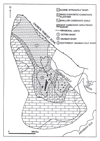
The Hanifa formation in the study area is comprised of eleven lithofacies originally identified by Saudi Aramco geologists from cores and used to construct a 3-D geological model that functioned as a template to control subsequent numerical modeling. Each lithofacies is characterized by specific porosity and permeability ranges, which could be utilized to predict the porosity and permeability distribution throughout the reservoir (Koepnick et al., 1994). Of the eleven identified lithofacies, the lime mudstone lithofacies 7 and 7.1 are non-reservoir, while the remaining nine lithofacies are reservoir facies. Generally, lithofacies could be used as an indicator of specific water depth and provide a key to the depositional setting in which it accumulated. Koepnick et al. (1994) identified forty-five geologic layers based on gamma ray and porosity markers that were correlated to 142 Berri Field Hanifa penetrations.
The general lithofacies trend is of decreasing porosity and permeability southwestward with the reservoir facies concentrated mainly on the northern shelf region of the reservoir while the more dense organic-rich and laminated lime mudstone are found in the southwestern region of the basin. Al-Khalifa (2001) stated that the "porosity in the Hanifa Reservoir is primarily intergranular with lesser moldic and intragranular porosity. Moldic porosity is the only secondary porosity that is significant, but has very low impact on the total reservoir compared to the intergranular porosity."
Table to left summarizes each lithofacies and depositional setting, while the sections below have brief descriptions of each of the depositional lithofacies. The source of core photos and microphotographs are from the 1991 Saudi Aramco-Mobile study (McGuire et al., 1993 and Koepnick et al., 1994).
Outer Ramp to Upper Ramp-Margin Lithofacies
Shallow water, high-energy lithofacies (skeletal conglomerate, skeletal intraclasts, and boundstones) are most prominent in the outer ramp and upper ramp margin (north-most) and represent the best reservoir facies. These lithofacies were deposited just below the sea level and extend to a depth just below the fair-weather wave base.
Lithofacies 2 - Skeletal/peloidal/intraclast grainstone-conglomerate
The depositional environment is interpreted to be a high-energy outer ramp and upper ramp-margin above fair-weather wave base. This lithofacies represents the highest permeability and porosity in the reservoir with an average porosity of 19%. This is the best reservoir lithofacies.
Lithofacies 2.1 - Skeletal/peloidal/intraclast packstone-conglomerate
The depositional setting is interpreted to be a high-energy outer ramp and upper ramp-margin to upper slope above fair-weather wave base, but in deeper waters than lithofacies 2. This lithofacies represents the intermediate permeability and porosity of the reservoir.
Lithofacies 3 - Massive skeletal/intraclast grainstone
The depositional setting is interpreted to be outer ramp and upper ramp-margin below fair-weather wave base. This facies has intermediate permeability
Lithofacies 3.2 - Cross-Bedded skeletal/intraclast grainstone
The depositional setting is interpreted to be upper ramp-margin below fair-weather wave base. This facies has the highest permeability
Lithofacies 3.3 - Burrowed skeletal/intraclast grainstone
The depositional setting is interpreted to be upper ramp-margin below fair-weather wave base. This facies has intermediate permeability.
Lithofacies 8 - Stromatoporoid/coral boundstone/rudstone without mud matrix
This biohermal buildup setting is interpreted to be outer ramp and above fair-weather wave base. This lithofacies represents the intermediate permeability and porosity of the reservoir.
Lithofacies 8.1 - Stromatoporoid/coral boundstone/rudstone with mud matrix
This biohermal buildups depositional setting is interpreted to be outer ramp above fair-weather wave base. This lithofacies represents the intermediate permeability and porosity in the reservoir.
Middle Ramp-Margin Slope lithofacies
To the southwest, shallow-water facies give way to margin slope lithofacies (skeletal packstone and wackestone) that represent intermediate-quality reservoir facies. These lithofacies are believed to have been deposited above the storm wave base and below the fair-weather wave base.
Lithofacies 5 - Skeletal packstone
The depositional setting is interpreted to be middle ramp-margin slope below storm wave base in the aerobic zone. This lithofacies represents a very low permeability and porosity in the reservoir.
Lithofacies 6 - Skeletal wackestone/mudstone
The depositional setting is interpreted to be middle ramp-margin slope below storm wave base in the aerobic zone below lithofacies 5. This lithofacies represents the very low permeability and porosity of the reservoir.
Basinal lithofacies
Further to the southwest there are the non-reservoir, dense lime mudstone basinal lithofacies that serves as source Rock for the overlying reservoirs or seal to the underlying reservoirs. These basin lithofacies were deposited in quiet anoxic water conditions as suggested by the organic-rich lime mudstone of this lithofacies. The lamination indicates a weak current in a not too deep-water depth (Droste, 1990).
The reader is referred to Wilson's idealized sequence diagram of standard facies belts for more details of this kind of interpretation.
Lithofacies 7 - Organic-rich laminated lime mudstone
The depositional setting is interpreted to be a basin with anoxic, low-energy water conditions. These Rocks form a non-reservoir facies. Bioturbation is subsequently minimal which contributes to the preservation of the organic matter. As expected, non-reservoir lithofacies are found in this part of the basin where permeability and porosity decrease with depth to values of 0% for both. This lithofacies is found in the deepest part of the formation and is always overlain by laminated lime mudstone. This is believed to be the source Rock for overlying reservoirs including the Jubaila and the Arab reservoirs. These lime muds also function as a seal for underlying Hadriya Reservoir.
> This lithofacies is characterized by low sonic velocity, and variable gamma ray (low to high to low with the high corresponding to the maximum organic matter content) (). Droste's (1991) study found that for this lithofacies the total organic carbon (TOC) amounts to 1-6% weight. A more recent study by Carrigan et al. (1995) determined that the average TOC in the Hanifa source Rock is 3% with reported contents as high as 13%. Their analysis of the organic contents found in this lithofacies matches the hydrocarbons found in the upper Jurassic reservoirs (in the Arab formation).
Lithofacies 7.1 - laminated lime mudstone
The depositional setting is interpreted to be of a basin below the storm wave base. This is a non-reservoir facies with 0% porosity and 0% permeability. This lithofacies functions as a seal for the underlying Hadriya Reservoir.
Droste's (1991) study found that this lithofacies has a total organic carbon (TOC) that amounts to less than 1% weight.
Correlation
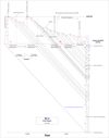
The diagram summarizes the sequence stratigraphic framework of the upper Hanifa sequence (shaded red). This 3rd order sequence spans a period of about 2 million years and is bounded below by a subaqueous hardground surface that caps the underlying Hadriya ramp while the top boundaformformformry is the basinal Jubaila lime mudstones (transgressive surface). The compilation of this diagram is based on the interpretation of McGuire et al. (1993). The bulk of the Hanifa reservoir was deposited during the highstand systems tract of the sequence, where it produced the shelfal skeletal conglomerates of the shelf.
The high-energy reservoir skeletal grainstones can be correlated mainly on the basis of lithofacies determined from core description, since the gamma ray log character provides no marked signal because the oxidizing conditions of the depositional setting removed the organic matter which would have concentrated the radioactive elements (McGuire et al., 1993). Shoaling upward parasequences and porosity logs were used to correlate the shallow parts of the reservoir (see later discussion of parasequences) while gamma logs were used for correlating the slope and basinal sections.
The ramp basin gently dips toward the SW with facies showing a gradual transition from biohermal on the shallowest part of the shelf into organic-rich lime mudstone within the deepest parts of the basin in the southwest ( is a diagram of interpreted depositional profile) with grainstones, packstones, and wackestone in the center of the basin. This depositional profile (ramp) was utilized as a guide in the interpretation process and to ensure that major surfaces (SB, mfs, ts) trend always follows the depositional profile of the basin (dipping southwestward).
After experimenting with various datums (reference surfaces to hang or to draw all surfaces from), it was concluded that the best stratigraphic datum to be used for correlation was the bottom transgressive surface that separates the Hanifa sequence from the Hadriya sequence below. The maximum flooding surface forms a good time line, but when it is identified, it follows the profile of the basin and is not horizontal. A reconstructed sea level surface is the ideal horizon. This datum can be constructed by identifying all time-equivalent lithofacies from all parts of the basin.
Three major types of surfaces were used for correlating the whole section. These are the bottom and the top transgressive surfaces bounding the Hanifa reservoir, the maximum flooding surface, and the shelf-wedge margin sequence boundary (SB-2). These surfaces represent time lines (are chronostratigraphic) and separate older Rocks below from younger Rocks above. sequence boundaries (SB) formed when there was a lowering of the relative sea level and there was a reduction of accommodation space to a minimum. A SB separates the highstand systems tract below from the lowstand systems tract (or in this case, shelf margin wedge systems tract) above. On the other hand, a maximum flooding surface (mfs) coincided with a maximum rate of rise in relative sea level and an increase of the accommodation space to the maximum. The mfs separates the transgressive systems tract below from the highstand systems tract above.
I. Shelf-margin wedge (SMW) sequence boundary, type-2 (SB-2)
An SB-2 is identified by a sudden Gamma Ray spike (high), which corresponds to an increase in porosity in the shelf margin to basin region. The SB-2 converges into a very thin interval in the upper ramp margin and can be recognized only by the trend of the lithofacies in the succession. According Kendall et al. (1991), shelf margin wedges aggrade upward when the sea level rises slowly causing the continual carbonate production and the margin to prograde seaward in response to the lack of accommodation space. Goldhammer et al. (1991) noted that a SB-2 develops during a time of maximum rate of long-term accommodation decrease and marks a turn around from progressively thinning upward cycles into thickening upward cycles (a SB-2 is identified on the basis of on the character of stacking patterns including cycle thickness, facies character, lateral geometry, and early diagenetic attributes) (Goldhammer et al., 1991).
II. The maximum flooding surface (mfs)
An mfs is identified in the section by a sudden gamma ray spike (see cross-section) on the basinal wells. However, an mfs becomes increasingly difficult to identify toward the shelf since only shallow shelf facies and no shales are present; never the less, the gamma ray spike can still be recognized. The best means of identifying the mfs within shallow part of the basin (outer ramp) is by identifying a definite change in stacking pattern in which the cycles change from deep facies (wackestone and packstone dominated) into shallow facies (skeletal intraclasts). This geometrical trend can also be observed by laterally moving shelfward.
III. Transgressive surface (ts)
The upper transgressive surface which separates the Hanifa formation from the overlying Jubaila formation is recognized by a uniform increase in gamma ray signal, an increase of sonic velocity, and a lowering of porosity. All these effects are a response to a sudden deepening (increase of relative sea level).
Parasequences; parasequence sets; and systems tracts
Van Wagoner et al., (1990) indicated that parasequences boundaries can be easily correlated regionally, and suggests therefore that parasequence boundaries are good surfaces for regional correlation of timelines. Van Wagoner et al., (1990) also reasoned that parasequences were deposited when the rate of (carbonate) sedimentation exceeds the rate of accommodation space; they argue that a Parasequence boundary (mfs) forms when the rate of accommodation space creation exceeds the rate of sediment supply (give-up and there is termination of the carbonate factory). The character of the parasequences differs on the basis of the behavior of the relative sea level during sediment deposition, particularly the abruptness of the sea level change and the position within the systems tract.
The figure above illustrates some typical parasequences found throughout the section with their predicted depositional settings and occurrences within the sequence.
In this x- section, the ideal parasequence found in the Hanifa section is described based on the observed lithofacies succession .
Shoaling-upward parasequences terminated by rapid sea level rise or a maximum flooding surfaces (mfs) (or using Kendall et al., 1991 terminology, give-up surface) are the basic genetic recognizable units in the section. The parasequences patterns and thickness are influenced by sea level fluctuation, rate of carbonate production, tectonic rate of subsidence, and subaerial exposure. No evidence of this latter was found in this section since it is believed that the shallower water sediment was being eroded and carried down slope. The parasequences are most useful here to detect relative-sea level fluctuation and to deduce a relative sea level on local scale and so then to be used for regional correlation (see discussion of Fischer Diagram below). parasequences also provide a key for confirming the major surfaces which cab used for correlating the shallow shelf section where the gamma log character is most ambiguous. For example, when a deeper lithofacies (i.e. lithofacies 5: skeletal packstone) overlies the shallow parasequences of shelf, then this can be used as an indication of sudden increase of the sea level and the initiation of the transgressive systems tract (TST).
Highstand Systems Tract (HST)
The parasequences thickness and composition is controlled largely by the deposition profile of the basin (in this case a gentle ramp). As a result, the aggrading-prograding parasequences of the HST thin toward the basin and gradually become indistinguishable as the section becomes mostly lime mudstone (forming a condensed section). On the other hand, HST parasequences are most easily distinguishable in the shallow region (north) of the study area where shallowing-upward cycles are capped by maximum flooding surfaces and sudden lithofacies changes from a shallow to a deep lithofacies. Consequently, the HST parasequences form the bulk of the reservoir in the north and center of the Hanifa formation and extend to center of the formation. These parasequences downlap on the mfs basin-ward and are truncated by the sequence boundary on the shelf.
Shelf-Margin Wedge (SMW)
The shelf-wedge margin systems tract (SMW) is bounded below by a type 2 sequence boundary (SB-2) and is identified by prograding shallow shelf lithofacies over the subaqueous sequence boundary. The prograding parasequences (layers) converge (thin) where they collect towards and on the shelf and thicken toward the basin. The central wells provide the clearest aggrading parasequences of the SMW and are used here for correlation throughout the field. The SMW parasequences onlap on the sequence boundary (SB-2) with thicker laminations (deposited within shallower water) in the basin and thin toward the shelf edge. The sequence boundary is recognized indirectly on the basis of a basin-ward shift of the lithofacies. The parasequences change in composition from deep lithofacies into progressively shallow lithofacies with thinner and thinner packstone and wackestone lithofacies in the shelfal parasequences with more and more skeletal intraclasts and conglomerates occurring within them. The basinal parasequences also experience the same gradual change as the relative sea level shallows and accommodation space decreases. The basinal parasequences also gradually lose the lime mudstone lithofacies composition to more packstone and wackestone and even skeletal intraclasts in the SMW. As a result, the SMW parasequences form the upper portion of the reservoir in the southwest region of the Hanifa formation.
Transgressive Systems Tract (TST)
The overlying TST parasequences are identified on the basis of the evidence of thin, back stepping parasequences overlying the shallow lithofacies on the shelf as a result of a drowning event (sea level rise). These parasequences progressively lose their shallow lithofacies contents to deeper lithofacies (deepening-upward) (see top of well # 014 in - regional cross section). The early TST parasequences form the uppermost units of the Hanifa reservoir in the northern region of the basin. The drowning surface marking the top of the Hanifa formation and the lower surface of the overlying Jubaila formation can also be identified by a sudden gamma ray log spike (high) marking deepening (significant change in lithology) and sudden decrease in porosity to very low value (5% or less) throughout the section. The lower boundaformformformry of the Upper Hanifa Reservoir is identified by a clear drowning surface, which is marked by a sudden increase in gamma ray log, and a drastic decrease in porosity. This surface also marks the top of the underlying Hadriya reservoir.
Sea Level Re-Construction from lithofacies succession
Fischer plots were used successfully to extract the 3rd-order and higher sea level fluctuations from high frequency cycles identified on the section. They illustrate the long-term accommodation changes similar to those described by Goldhammer et al. (1991) and "reveal systematic changes in accommodation by plotting successive deviations in cycle thickness from the average cycle thickness" (Read and Goldhammer, 1988). Fischer diagrams (plots) have been constructed from two wells to determine the feasibility of constructing the third order sea level curve and then comparing it to the Haq et al (1987) sea curve to establish a match. Another important objective was to use the plots to discern the role of subsidence (when plots of various parts of the region are compared). The selected wells represent the shallowest part of the section (well # 014) and the center part of the section (well # 006). Selecting wells from the deep part of the section was not useful since identifying parasequences based on lithofacies succession was not possible because the lithostratigraphy consisted only of lime mudstone.
The sea level curve rise-fall illustrates the relationship between sea-level changes and cycle thickness in response to the creation of accommodation space. The two diagrams shown here clearly show that during a sea-level rise, the cycle thickens; on the other hand, when sea level falls, the cycle thins.
Three fourth-order sequences were identified after constructing the Fischer diagrams. Each of these sequences is bounded by a type-2 sequence boundary and is recognized on the diagram at the maximum sea level fall inflection point. Each of the 4th order sequences has a recognizable maximum flooding surface (which corresponds to the 3rd order sequence mfs in one of these sequences). An important observation is that the maximum flooding surface (mfs) identified based on the recreated sea level curve (at the point of maximum cumulative cycle thickness point) has a different position from the mfs identified on the section. The first cycle of each Fischer diagram is very thick due to the fact that deposition started with thick basinal cycle (lime mudstone) at the base of the section. However, both reconstruct 3rd order curve faithfully and represent the actual relative sea level fluctuation position that occurred when these cycles were deposited.
Conclusions
This analysis confirms the conclusions of previous work that the bulk of the Hanifa reservoir is composed of skeletal conglomerates which were deposited on the relatively high-energy shelf (northern region of the formation) within the highstand systems tract of the upper Hanifa sequence. We also found that the contemporaneous organic-rich lime mudstones were deposited on the southern region of the basin during late transgressive systems tract and during the highstand systems tract under quiet and anoxic water conditions. The lithofacies shift from the shelf to basin is gradual and grades through the identified eleven lithofacies in response to the changes of the relative sea level in which they accumulated. The deposition of these lithofacies was also greatly affected by the depositional profile of the basin, which was very gentle ramp with an intrashelf basin to the south. The lithofacies distribution in the basin enables the prediction of the best reservoir facies, mainly to the north, and the interpolation of the intermediate lithofacies. The Fischer diagrams enabled the reconstruction of the sea level in the peritidal shelfal regions and generally mimicked the Haq eustatic sea level curve. The Fischer diagrams also revealed three fourth-order sequence that were not identified earlier.
Future Work
A more in-depth analysis of the basin should be possible if more well data were made available. In such a study, objectives could include the construction of porosity models from which the prediction of lithofacies, and the construction of 3-D lithofacies models might result. Additionally, a more precise sea level curve based on Fischer diagrams might be constructed if more wells were available in the shallow shelf region of the basin to the north.