| Phantom Wells | ||||||||||||||||||
| PSEUDO | A | A | A | A | A | A | A | B | B | B | B | B | C | C | C | C | C | C |
| WELL | MFS | TS | TST (NET SS) | SB | IVF (NET SS) | HST (NET SS) | MFS | TS | TST (NET SS) | SB | IVF (NET SS) | HST (NET SS) | MFS | TS | TST (NET SS) | SB | IVF (NET SS) | HST (NET SS) |
| a | 4610 | 4620 | 0 | 4620 | 0 | 19 | 4680 | 4702 | 0 | 4702 | 0 | 10 | 4774 | 4780 | 0 | 4780 | 0 | 0 |
| b | 4252 | 4270 | 2 | 4270 | 0 | 20 | NP | NP | NP | NP | NP | NP | NP | NP | NP | NP | NP | NP |
| c | 4135 | 4150 | 2 | 4150 | 0 | 16 | 4200 | 4220 | 1 | 4220 | 0 | 2 | 4270 | 4291 | 9 | 4328 | 35 | E |
| d | 4541 | 4560 | 3 | 4560 | NA | 23 | 4629 | 4640 | 1 | 4640 | 0 | 8 | 4707 | 4739 | 0 | 4739 | 0 | 12 |
| e | 4293 | 4322 | 15 | 4345 | 22 | NA | NP | NP | NP | NP | NP | NP | NP | NP | NP | NP | NP | NP |
| f | 4225 | 4235 | 1 | 4235 | 0 | 10 | 4270 | 4281 | 2 | 4335 | 54 | 0 | 4337 | 4347 | 0 | 4347 | 0 | 45 |
| g | 4138 | 4160 | 6 | 4160 | 0 | 12 | 4196 | 4230 | 10 | 4265 | 35 | 0 | 4280 | 4300 | 12 | 4300 | 0 | 30 |
| h | 3887 | 3894 | 0 | 3894 | 0 | 0 | 3911 | 3958 | 5 | 3988 | 30 | 0 | 3990 | 3995 | 3 | 3995 | 0 | 36 |
| I | 4400 | 4412 | 0 | 4412 | 0 | 29 | 4480 | 4492 | 1 | 4492 | 0 | 30 | 4547 | 4556 | 2 | 4556 | 0 | 53 |
| j | 4210 | 4230 | 7 | 4290 | 60 | 0 | 4299 | 4335 | 14 | 4370 | 35 | 0 | 4379 | 4400 | 6 | 4400 | 0 | 41 |
| k | 4291 | 4329 | 25 | 4361 | 31 | 0 | 4369 | 4378 | 0 | 4378 | 0 | 10 | 4426 | 4442 | 7 | 4442 | 0 | 41 |
| l | 4675 | 4692 | 2 | 4692 | 0 | 9 | 4741 | 4752 | 1 | 4752 | 0 | 6 | 4810 | 4837 | 4 | 4837 | 0 | 29 |
| m | 4879 | 4885 | 0 | 4885 | 0 | 0 | 4935 | 4940 | 0 | 4940 | 0 | 0 | 5000 | 5028 | 0 | 5028 | 0 | 0 |
| n | 4339 | 4363 | 10 | 4383 | 20 | 13 | 4405 | 4449 | 17 | 4460 | 11 | 0 | 4464 | 4496 | 17 | 4571 | 76 | 0 |
| o | 4301 | 4326 | 10 | 4326 | 0 | 22 | 4359 | 4382 | 17 | 4427 | 44 | 0 | 4430 | 4448 | 13 | 4448 | 0 | 15 |
| p | 4506 | 4530 | 13 | 4530 | 0 | 20 | 4560 | 4574 | 5 | 4574 | 0 | 42 | 4632 | 4662 | 22 | 4662 | 0 | 19 |
| q | NA | NA | NA | NA | NA | NA | NA | NA | NA | NA | NA | NA | NA | NA | NA | NA | NA | NA |
| r | 4758 | 4763 | 0 | 4763 | 0 | 6 | 4793 | 4801 | 0 | 4801 | 0 | 0 | 4850 | 4873 | 0 | 4873 | 0 | 0 |
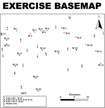
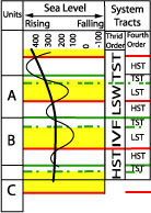
This spread sheet lists "Phantom" or "Pseudo" well localities for which there are no well logs available on the web site. Included on the sheet are the thickness of the various system tracts and their lithology. This can be added to the compilation you make from the well logs and use in the construction of the maps of the depositional setting of each of the system tracts. For instance well "a" (see base map for location) is subdivided into units A, B and C (see the sea level curve). Unit A is capped by a MFS (maximum flooding surface), and is subdivided by a TS (transgressive surface) and a SB (sequence boundary) and underlain by a further MFS (maximum flooding surface). The TST for Unit A (transgressive system tract) is composed of shale with no sand accumulation. The IVF (incised valley fill) has no thickness. A similar nomenclature applies to the other units, wells and system tracts.